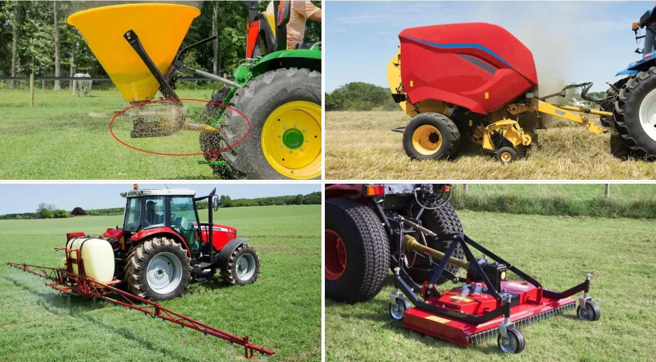
Every piece of farm equipment that attaches to a tractor and needs rotational power — mowers, balers, tillers, spreaders, grain augers — depends on a single mechanical link to receive that power: the PTO shaft system. Despite being one of the most critical components in agricultural machinery, PTO systems are frequently misunderstood, poorly maintained, and improperly matched to their applications, leading to premature failure, costly downtime, and in serious cases, dangerous accidents.
This guide provides a thorough understanding of how PTO shaft systems work, what components they consist of, how they integrate with other tractor systems, and how to select and maintain them properly.
What Is a PTO Shaft and What Does It Do?
PTO stands for Power Take-Off. It is a mechanical system that transfers rotational energy from a tractor engine to an attached implement. The tractor PTO output stub — a splined shaft protruding from the rear of the tractor — rotates at a fixed speed when engaged. The PTO drive shaft connects this stub to the implement input shaft, typically through a gearbox that converts speed and direction as needed.
Without a PTO system, a tractor would only be able to pull implements passively. With PTO, the tractor becomes a mobile power source capable of driving rotary cutters, hay balers, snow blowers, post hole diggers, fertilizer spreaders, and dozens of other powered attachments.
The 5 Core Components of a PTO Drive Shaft Assembly
A complete PTO drive shaft assembly is not a single piece — it is a system of interdependent components. Understanding these parts is essential for correct selection, installation, and troubleshooting.
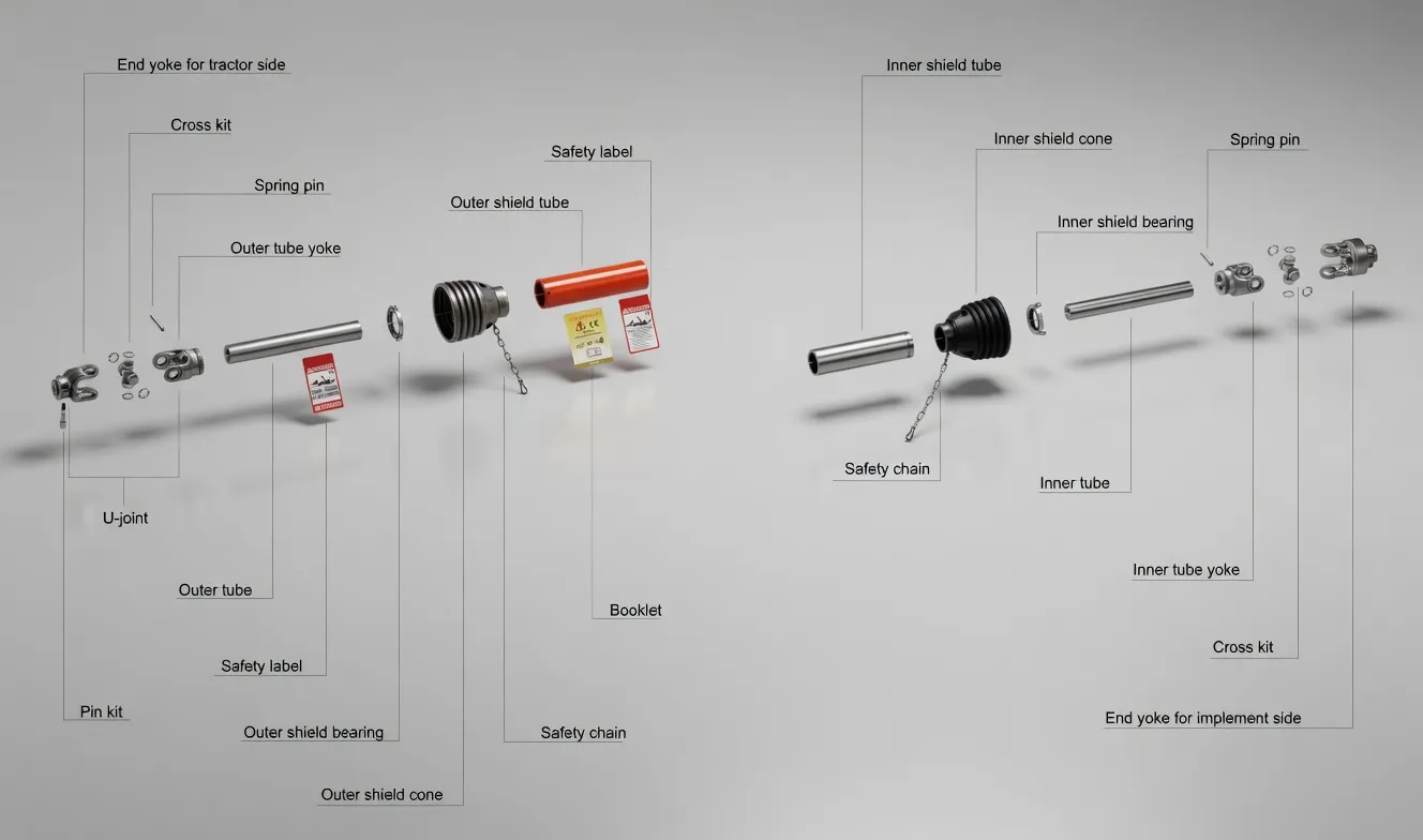
PTO shaft structure: yokes, universal joints, telescopic tubes, and safety shield working together as a system
1. Yokes (Input and Output)
The yokes are the connection points at each end of the shaft. The tractor-side yoke slides onto the PTO output stub and is secured by a locking mechanism — push pin, interfering bolt, or ball detent depending on the series. The implement-side yoke connects to the gearbox or implement input shaft. Yoke designs vary by PTO series, with push-pin style being most common for quick connection in agricultural applications.
2. Universal Joints (Cross Joints)
Universal joints allow the shaft to transmit power at an angle. Since the tractor PTO output and the implement input shaft are rarely perfectly aligned — especially as the implement moves up and down — the U-joints compensate for angular misalignment. Standard joints handle angles up to 15–25 degrees. For greater angularity, wide-angle PTO joints capable of 80 degrees or more are available.
3. Shaft Tubes (Outer and Inner Profile)
The shaft tubes transmit torque between the two universal joints. PTO shafts use profiled tubes — not round — to enable torque transmission. Common profiles include triangular (lemon), star, and splined configurations. The choice of profile affects torque capacity, smooth running characteristics, and compatibility with the yoke fittings at each end.
4. Telescopic Section (Sliding Connection)
The telescopic section allows the shaft to change length as the distance between tractor and implement varies — when turning, driving over uneven ground, or raising the three-point hitch. The inner and outer tubes slide within each other while maintaining torque transmission through their matching profiles. Proper greasing of this sliding interface is one of the most important maintenance tasks for PTO shaft longevity.
5. Safety Shield (Guard)
The safety shield is a plastic or composite cover that surrounds the rotating shaft and universal joints, preventing accidental human contact. PTO shafts rotate at 540 or 1,000 RPM and can entangle clothing or limbs in a fraction of a second. In the European Union, CE legislation mandates specific shield designs and coverage requirements. Never operate a PTO shaft with a missing or damaged guard.
PTO Speed Standards: 540 RPM vs 1,000 RPM
PTO shaft with universal joints in a typical agricultural power transmission application
Tractor PTO systems operate at standardized speeds:
540 RPM
The older and more common standard, used by the majority of small-to-medium implements: rotary mowers, feed mixers, small balers, and light-duty tillers.
Spline: 6-spline, 1-3/8″ (35mm) diameter
1,000 RPM
Designed for high-power implements requiring greater speed: large square balers, forage harvesters, and high-capacity grain carts.
Spline: 21-spline, 1-3/4″ (45mm) diameter
The two configurations are physically incompatible — an intentional safety design preventing accidental mismatching. Some modern tractors offer dual-speed PTO (both 540 and 1,000) or economy PTO (540E / 1000E), which achieves the standard implement speed at lower engine RPM to save fuel. When selecting a PTO shaft for agricultural machinery, always verify that the spline count, diameter, and speed rating match your tractor output.
How the PTO System Works with Other Tractor Systems
The PTO shaft does not operate in isolation. It is one element in a larger integrated power transmission network that also includes the hydraulic system, the implement gearbox, and the tractor drivetrain.
PTO + Gearbox: Speed and Direction Conversion
Most PTO-driven implements require an output speed different from the PTO’s fixed RPM. A gearbox mounted on the implement converts the input speed to the required tool speed. For example, a rotary mower might use a 1:1.47 ratio right-angle gearbox to reduce 540 RPM input to approximately 367 RPM at the blade spindle. The gearbox also changes the axis of rotation — typically from horizontal (PTO shaft) to vertical (mower blades) — using bevel gears.
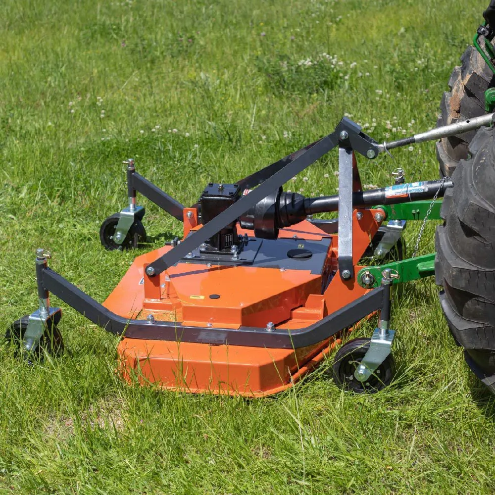
A right-angle gearbox converts PTO rotational input into the speed and direction required by the implement
PTO + Hydraulic System: Rotational Power Meets Linear Force
While the PTO shaft delivers rotational power to drive the implement working mechanism, the tractor hydraulic system provides the linear force needed to raise, lower, tilt, and position the implement. On a disc mower, the PTO drives the cutting discs through the gearbox, while a hydraulic cylinder lifts the mower head for transport. On a round baler, the PTO drives the bale chamber rollers while hydraulic cylinders open the tailgate for bale ejection.
This means most PTO-driven equipment simultaneously requires two types of power transmission components: a PTO shaft assembly for rotational energy and hydraulic cylinders for linear motion. For equipment builders sourcing both PTO components and hydraulic cylinders, integrated suppliers like SSJ Group can streamline procurement by providing both product categories from a single manufacturing source — reducing lead times, simplifying quality management, and ensuring mechanical interface compatibility across the drivetrain.
PTO + Overload Protection: Clutches and Shear Bolts
PTO systems are protected against sudden overloads by one of two mechanisms. A friction clutch (slip clutch) allows the shaft to slip momentarily when torque exceeds a preset threshold, absorbing shock without damaging the driveline. A shear bolt is a sacrificial pin designed to break under overload, disconnecting the shaft to prevent gearbox damage. Friction clutches are more convenient but more expensive; shear bolts are cheaper but require manual replacement after each event.
PTO Shaft Selection: What to Check Before You Buy
Choosing the wrong PTO shaft can result in premature failure, equipment damage, or safety hazards. Verify these parameters before purchasing:
✓
PTO speed — 540 or 1,000 RPM, matching your tractor output specification
✓
Spline count and diameter — 6-spline 1-3/8″ (540) or 21-spline 1-3/4″ (1000)
✓
Closed length and max extension — Must fit the tractor-to-implement distance in raised and working positions
✓
Torque rating — Must exceed max implement demand including transient overloads
✓
Tube profile — Triangular (lemon), star, or splined — must match yoke fittings on both ends
✓
Overload protection — Slip clutch or shear bolt based on application and preference
✓
Safety shield compliance — Must meet CE/EC requirements for the European market
PTO Shaft Maintenance Essentials
A well-maintained PTO shaft can last many years. A neglected one can fail catastrophically in a single season. Follow this routine before each season and at regular intervals during heavy use:
Grease the universal joints — every 8–10 operating hours. Use lithium-based EP grease applied through the U-joint fittings until fresh grease appears at all four bearing caps.
Grease the telescopic section — separate inner and outer tubes, clean off old grease, and apply a thin film of fresh grease over the full profile length. This prevents galling and ensures smooth telescoping.
Inspect the safety shield — check for cracks, missing segments, or bearings that no longer rotate freely. Replace immediately if damaged.
Check U-joint play — grip the shaft on either side of a joint and rock it. Perceptible play indicates worn bearings that should be replaced before they seize.
Verify yoke locking — ensure push pins snap fully into position and locking collars are secure. A yoke that separates during operation causes catastrophic damage.
Inspect the full driveline — when servicing the PTO shaft, also check the gearbox oil level, inspect hydraulic hoses and cylinders for leaks, and verify all guards are properly installed.
When to Replace Your PTO Shaft
PTO shafts should be replaced — not repaired — when any of the following conditions exist: U-joint bearing cups are worn through or seized; shaft tubes are bent, cracked, or show significant profile wear; the telescopic section no longer slides smoothly even after cleaning and re-greasing; yoke ears are cracked or pin holes are elongated; or the safety shield is too damaged for replacement guards to be sourced.
As a general rule, if the repair cost exceeds 50–60% of a new replacement, purchasing new is the better investment in both economics and safety.
For questions about PTO shaft specifications, compatibility, or pricing, contact our team for expert assistance.